NASA Glenn H.S. Engineering Institute
July 2025
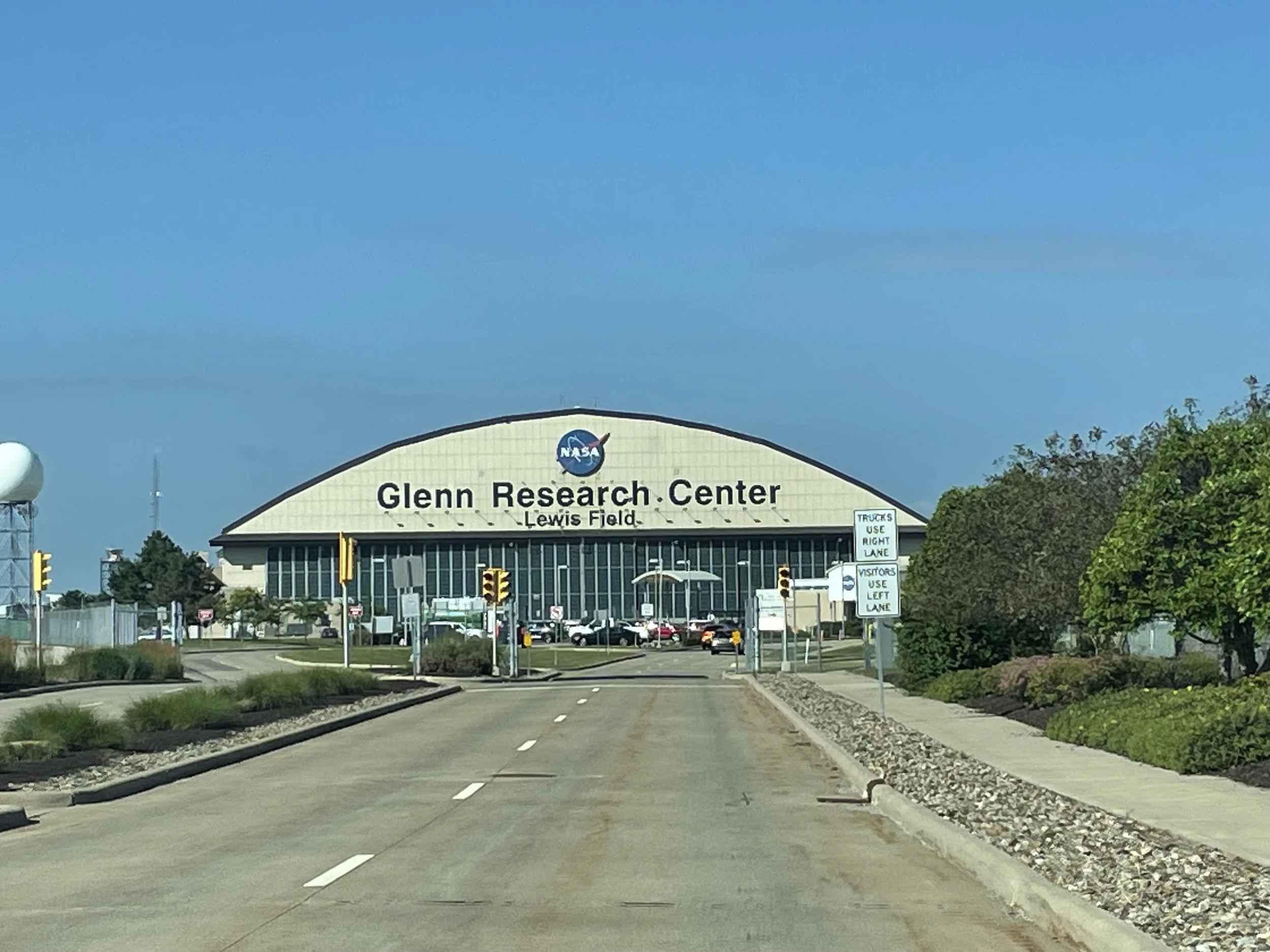
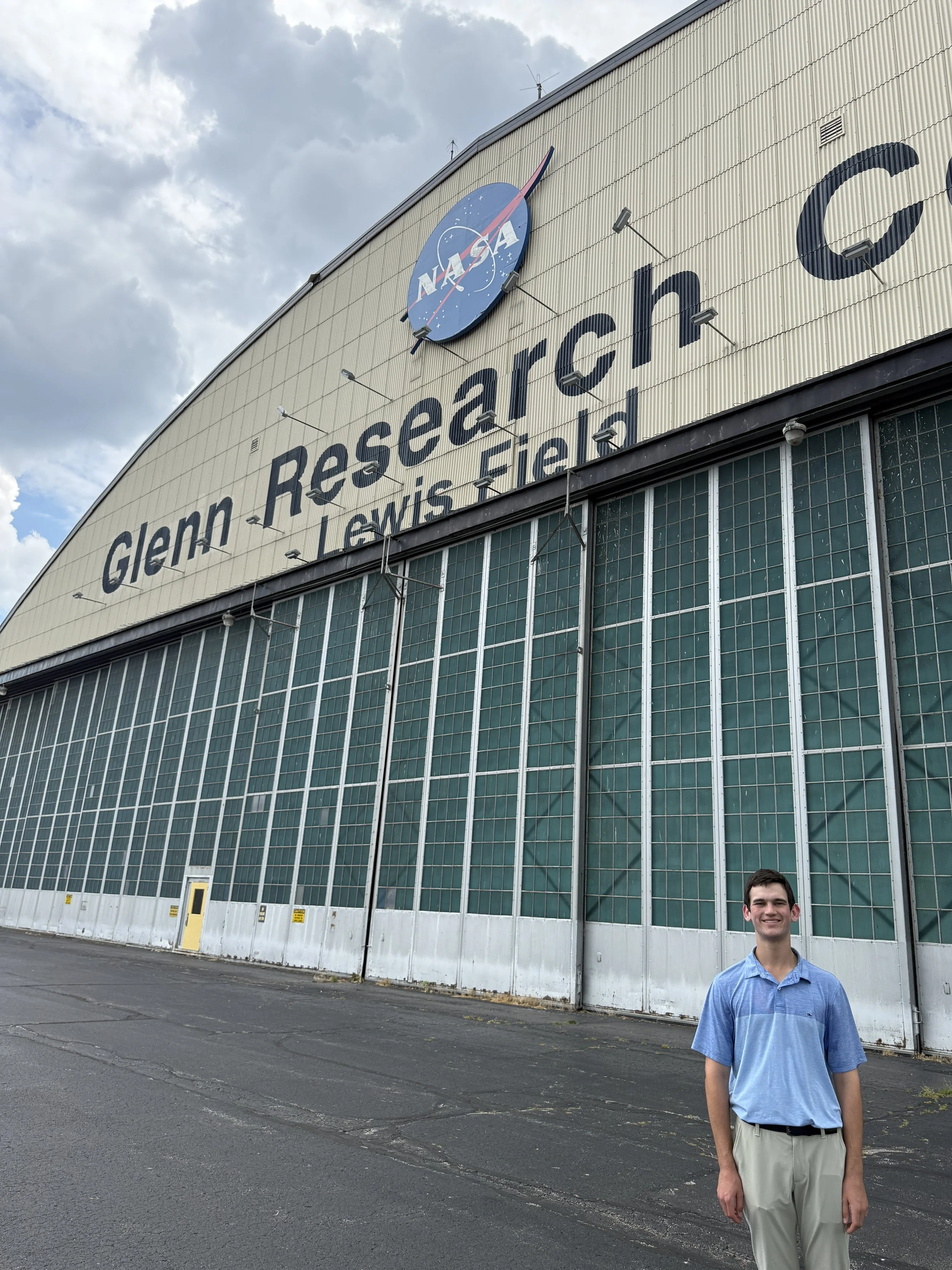
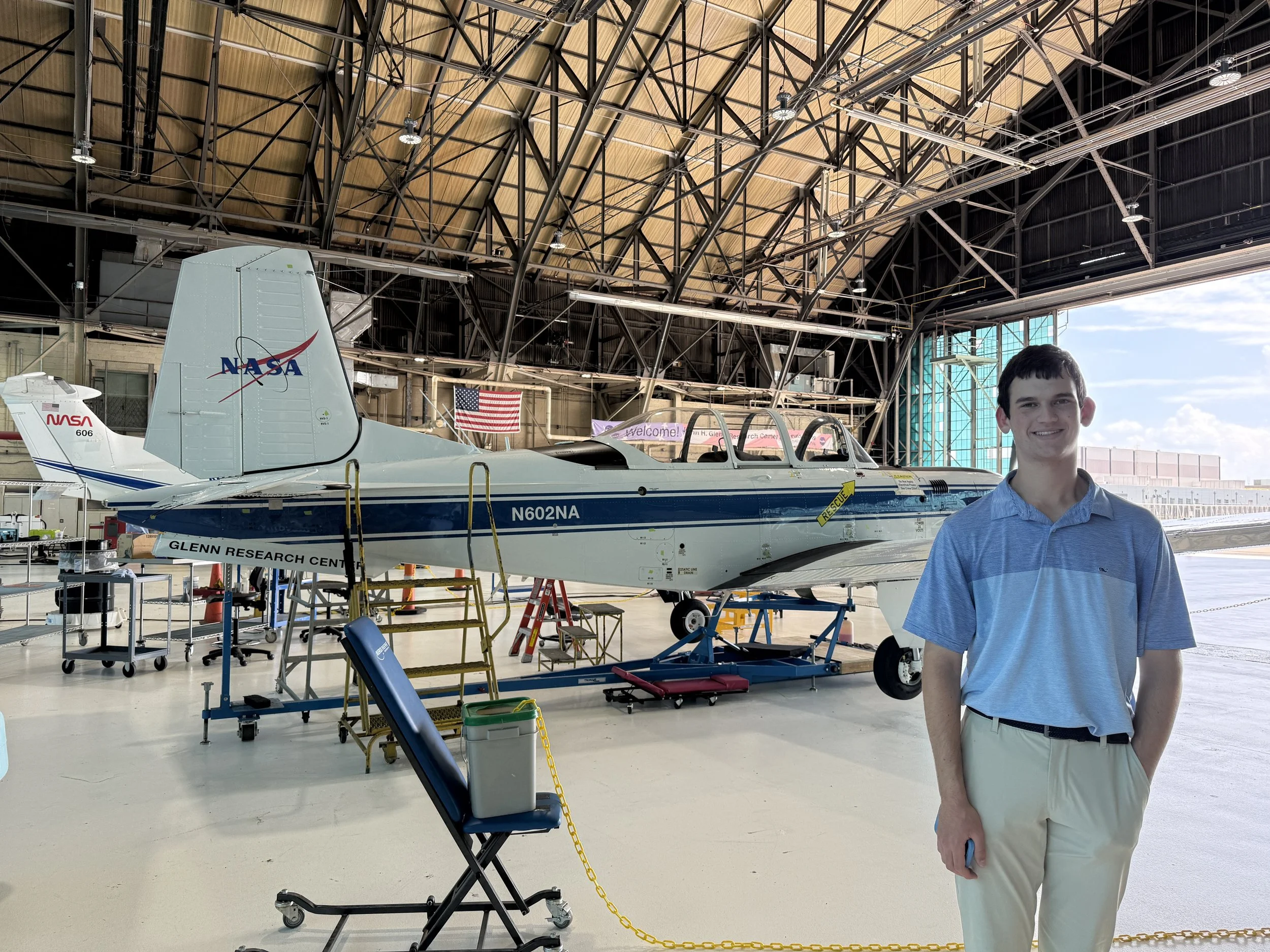
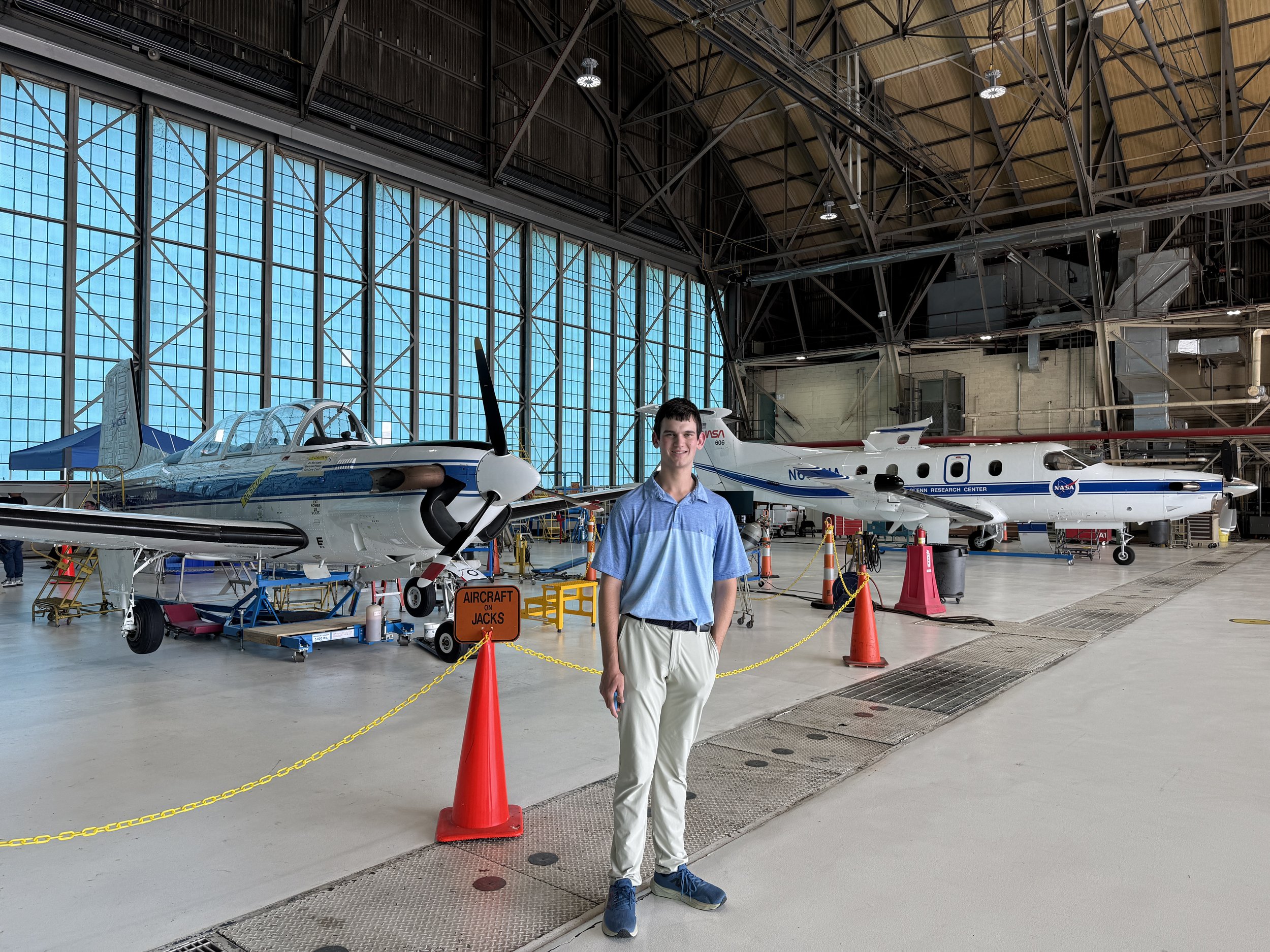
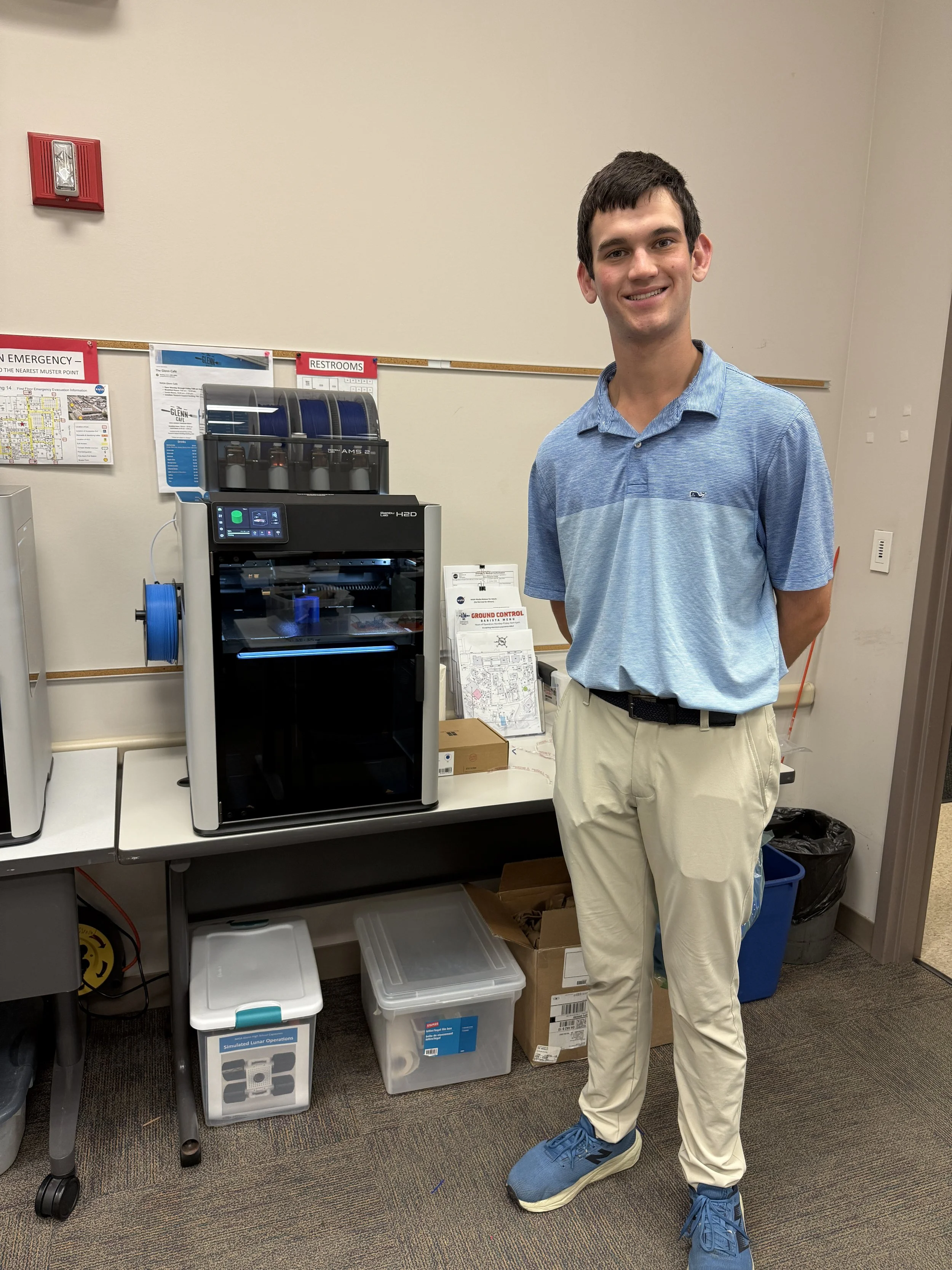
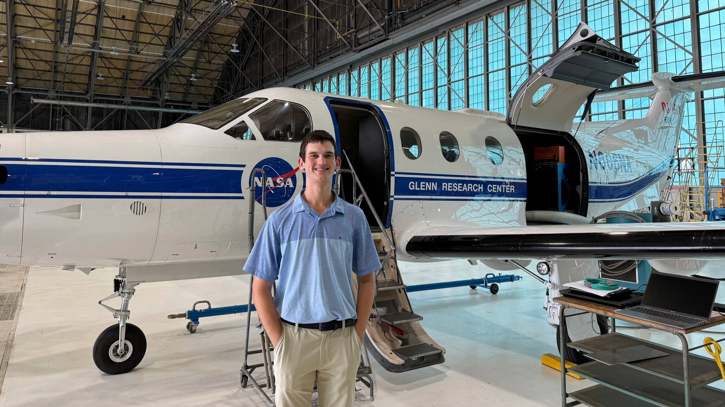
I was selected from a national pool of applicants to participate in an on-site intensive at the NASA Glenn Research Center. We visited facilities, learned about ongoing research, and spent the majority of our time working on engineering projects inspired by the real work done at the center.
SLOPE Lab
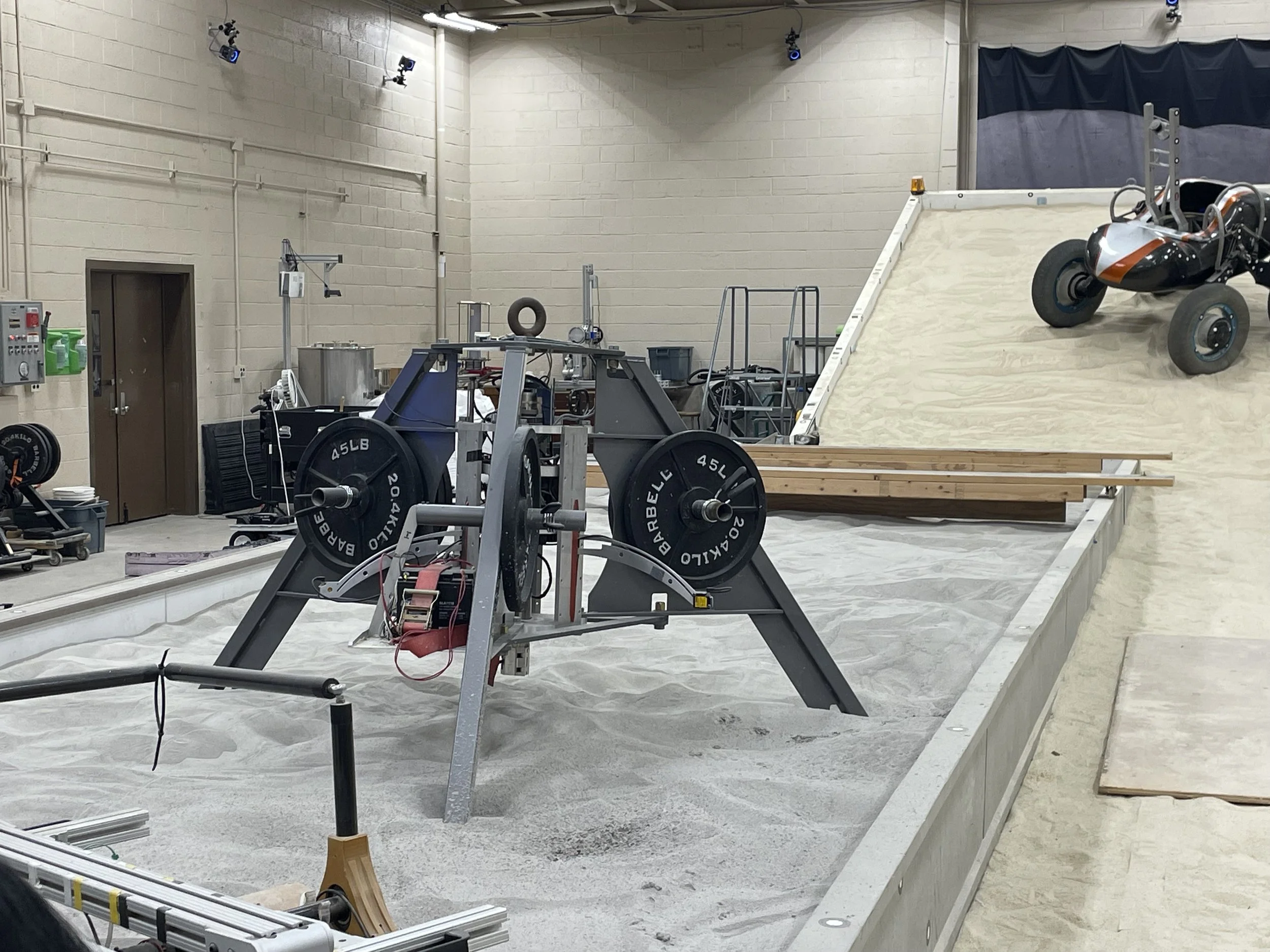
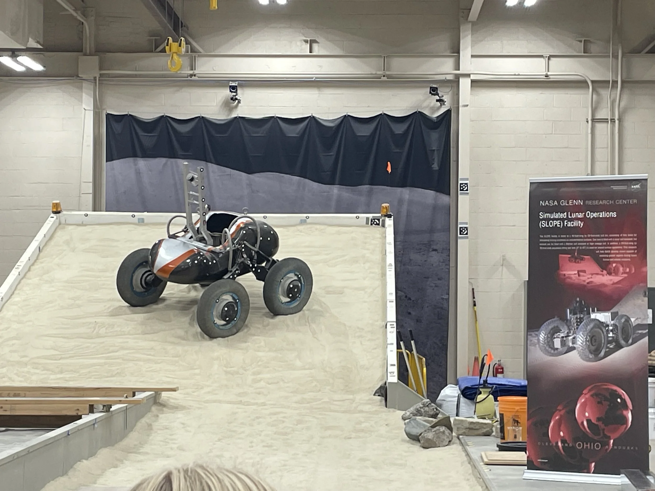
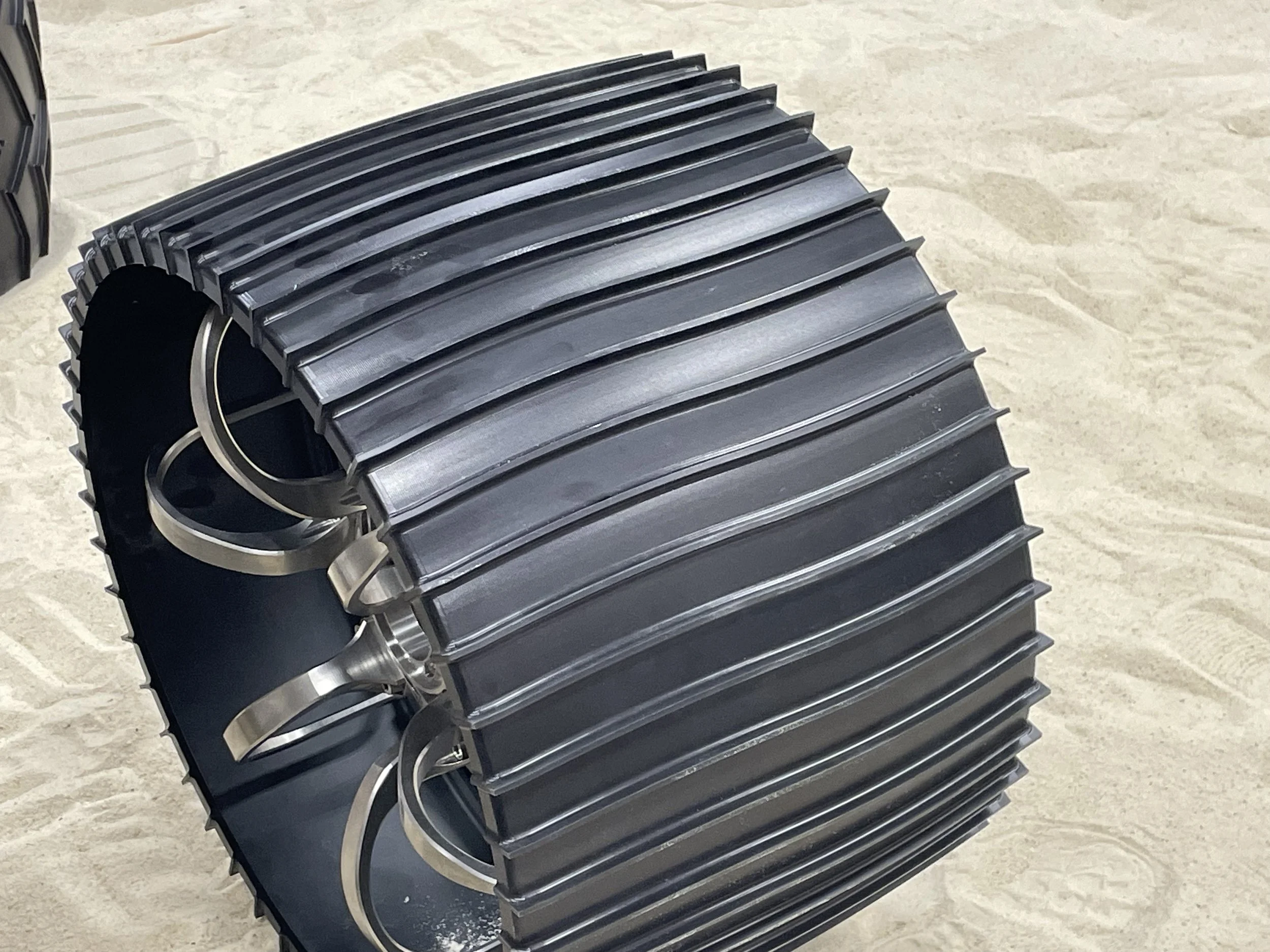
We visited the SLOPE (Simulated Lunar Operations) Lab, where NASA engineers design and test rover wheels, evaluating grouser performance and wheel construction in a variety of extraterrestrial regolith environments. A grouser is a raised lug on a wheel that improves vehicle traction. Prominent wheels tested at this facility include the wheels of the legendary Lunar Roving Vehicle, used on Apollo 15, 16, and 17. Other wheels tested include Curiosity’s and Perseverance’s rover wheels, as well as wheels for the VIPER lunar rover project.
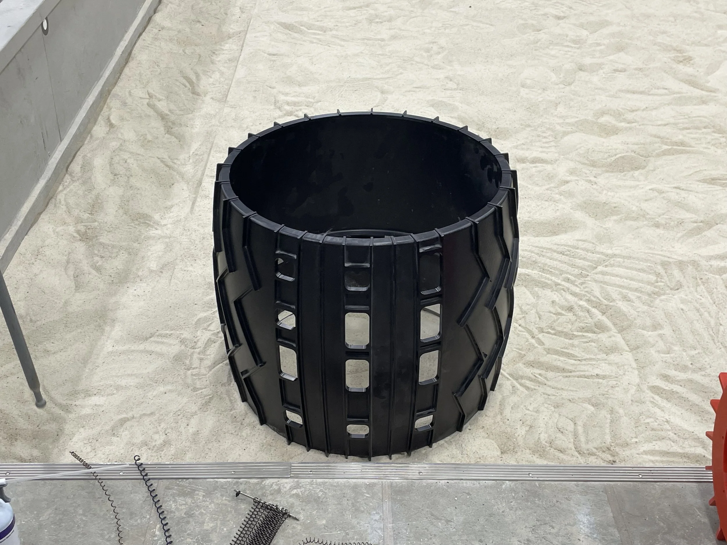
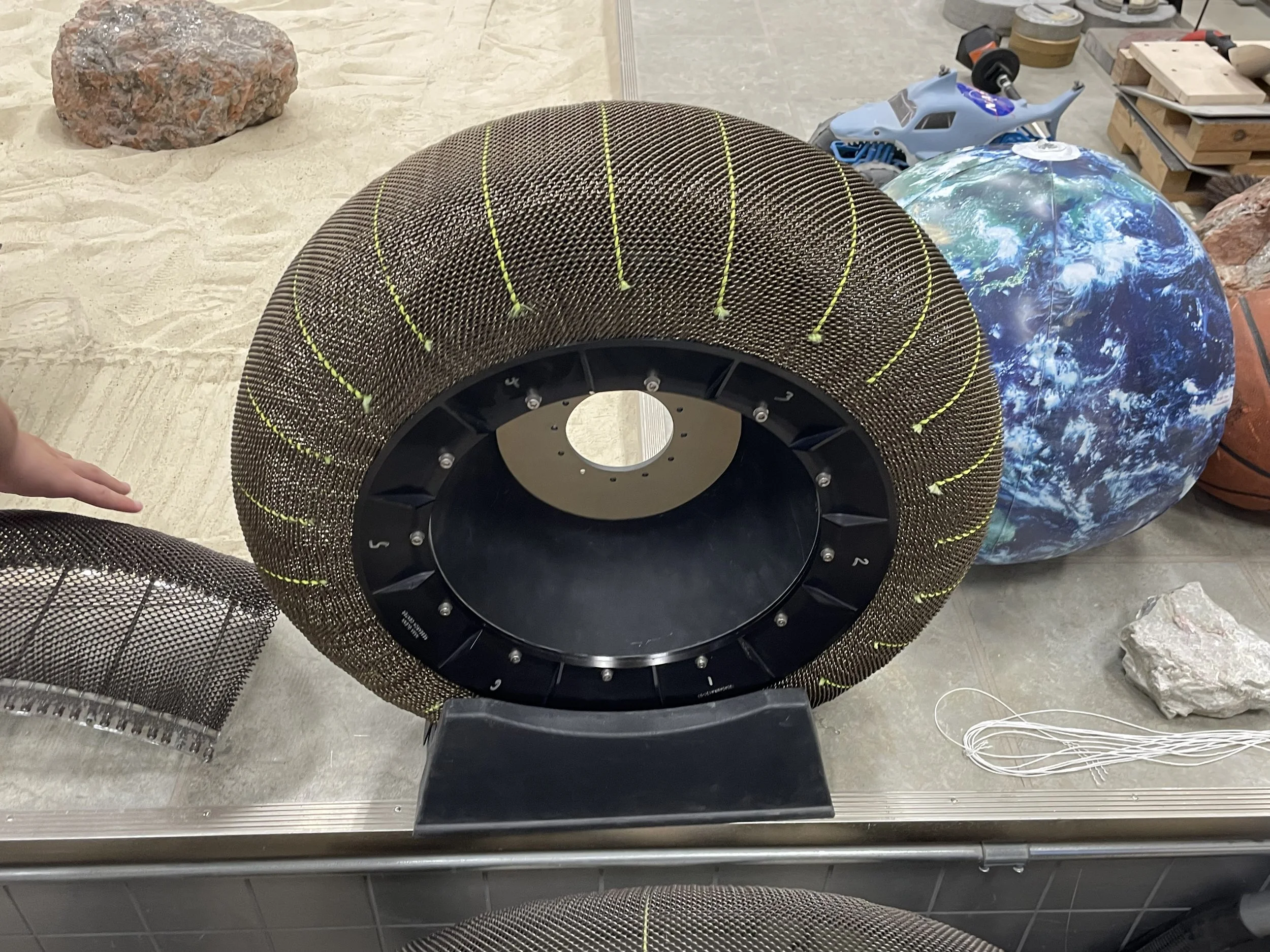
To the top right is a photo of a flight-ready backup wheel for the Perseverance rover. The wheel is machined from a billet of aluminum and is as thin as a credit card in certain spots. The spokes and hub are all machined from titanium, and in total, the wheel cost $250,000.
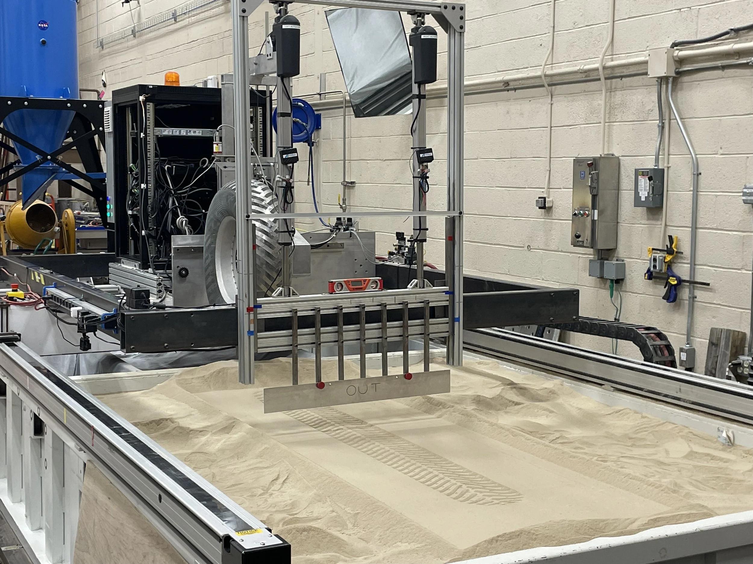
We also saw the apparatus used to test rover wheels, shown at the bottom right. A gantry moves the wheel forward independently of its rotation so that scientists can induce controlled slip to test rover performance in a variety of circumstances. This has partly inspired my apparatus for the 2026–2027 USIYPT “Friction On a Roll” problem.
Information credit: NASA Glenn H.S. Engineering Institute
Custom Wheel Design
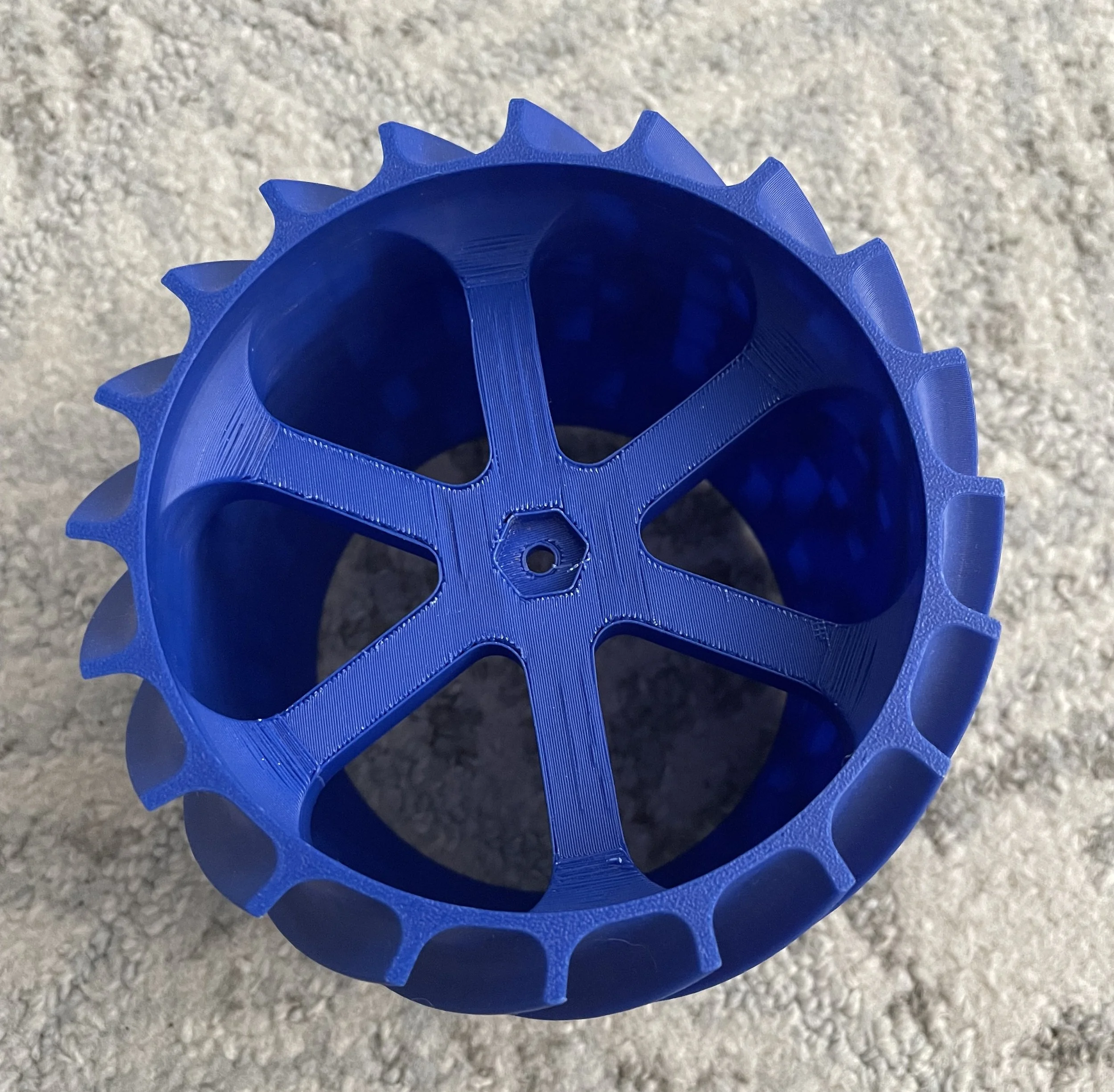
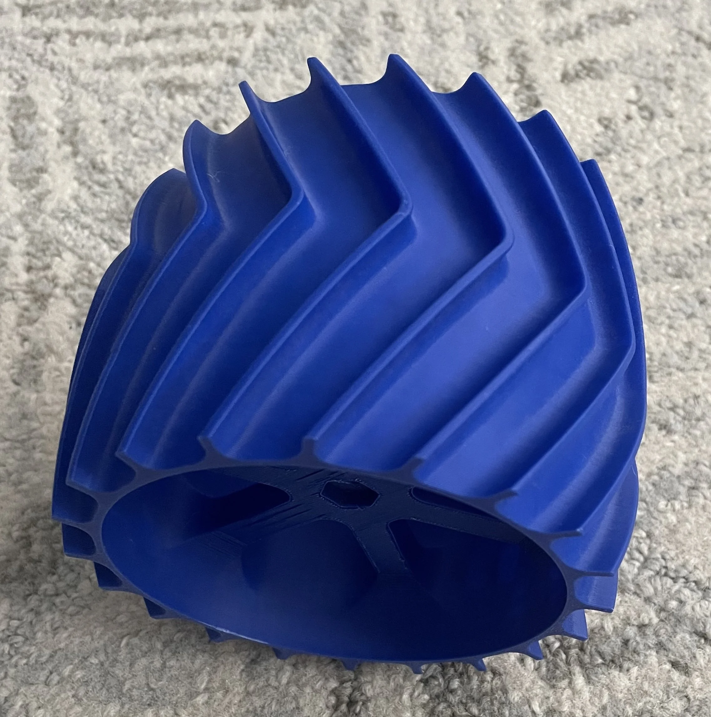
This was the main project of the intensive. First, we drew inspiration from the wheels of the Curiosity rover, the Perseverance rover, and the Apollo Lunar Roving Vehicle. Next, we designed our own grouser tread to carry weight plates up an angled sand incline. My team won by carrying 12.5 lb up the incline. We took a rigorous approach to our wheel design, examining Inotsume et al.’s 2014 paper “Analysis of Grouser Performance to Develop Guidelines for Design for Planetary Rovers” to identify the optimal height, width, spacing, and angle of chevron-shaped grousers. We settled on a 30° chevron design with grousers 5 mm thick and 8 mm tall.
We learned that grousers operate differently from tire tread and dig into the regolith to leverage the regolith’s own internal mechanical resistance to propel the rover forward. The resulting net forward force, called “drawbar pull,” depends on grouser geometry. Well-designed grousers reduce vehicle sinkage and wheel slip to prevent vehicles from getting stuck. A famous example comes from the Spirit rover on Mars, which became stuck as its wheels sank into the regolith. This highlights the importance of optimized grouser design, which can make or break interplanetary missions.
Information credit: NASA Glenn H.S. Engineering Institute
The AAPL
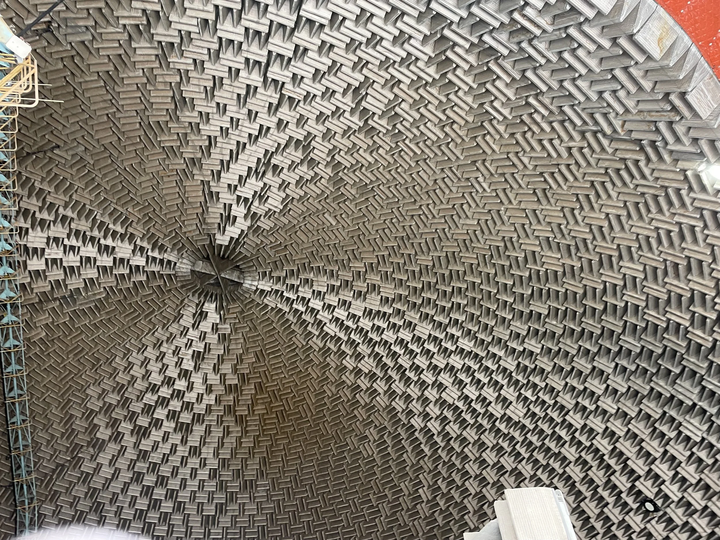
We also visited the Aero-Acoustic Propulsion Laboratory (AAPL), the site for testing and examination of air-breathing engine acoustics at NASA Glenn. It is a 65-foot-radius dome and is covered in sound-dissipation fiberglass wedges.
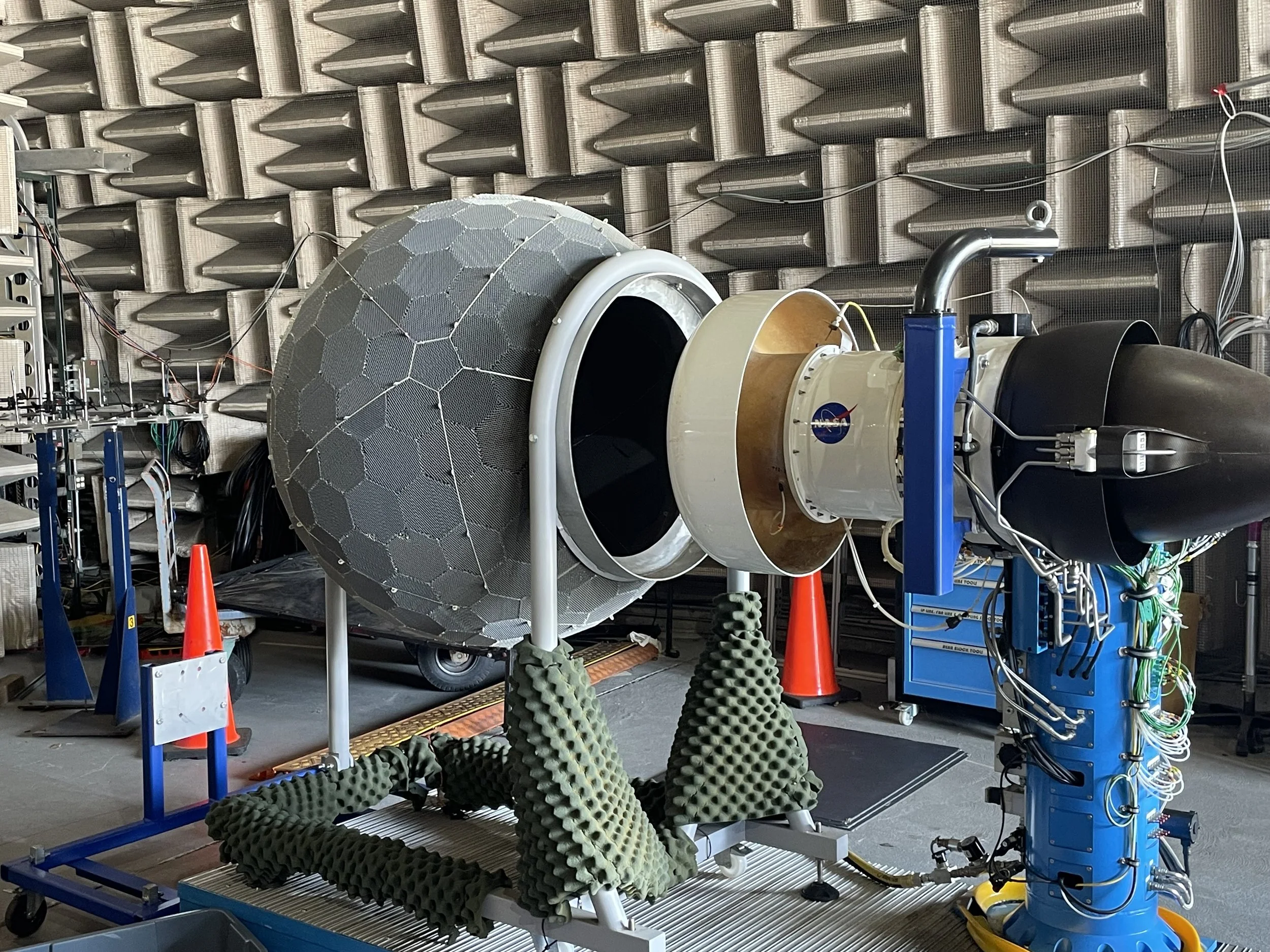
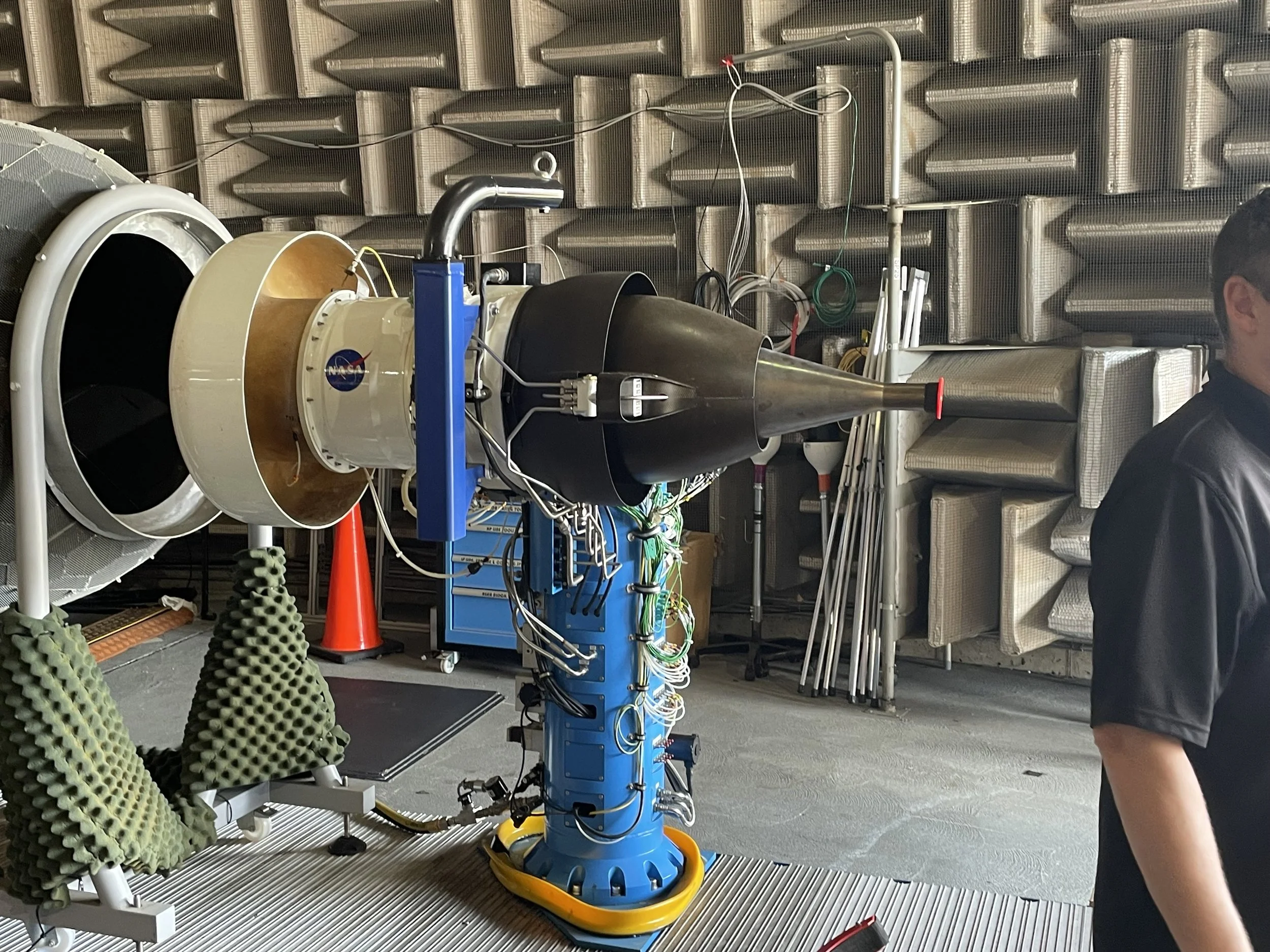
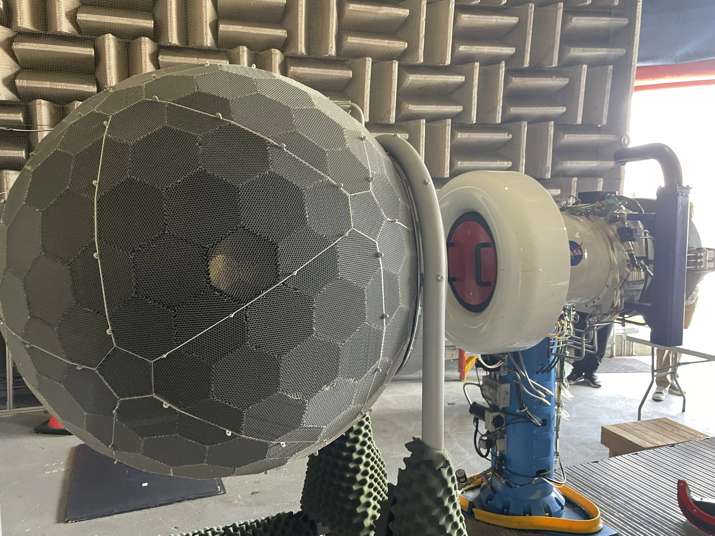
Among the engines we saw prepared for testing was the DGEN Aero-Propulsion Research Turbofan, based on the DGEN 380 commercial engine, with a bypass ratio of 7.6 and 570 lb of thrust. See the bottom-right image. This engine, which is designed for 3,638–4,740 lb aircraft, is a testbed for NASA’s explorations into aeroacoustic damping. Another engine tested there was the FJ44-3A turbofan. With 2,820 lb of thrust, this engine is used on light business jets.
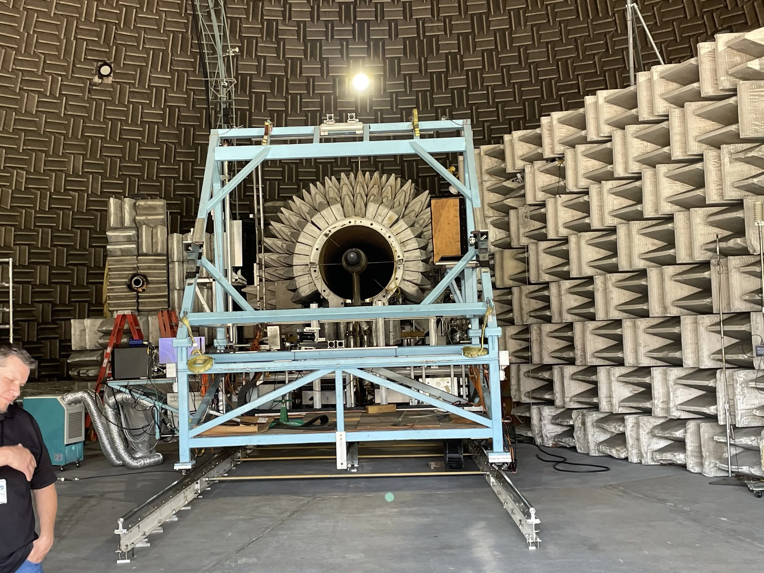
Inside the AAPL is the Nozzle Acoustic Test Rig (NATR). This is a free-jet wind tunnel and is unique in its ability to analyze flow properties and acoustics simultaneously. For a photo, see the top-right image. Companies and government organizations can test different-scale nozzle designs to optimize for both performance and acoustics.
We 3D-printed our own damping inserts for an impedance tube, and my two designs were inspired by nature: waving pond reeds and a honeycomb. The honeycomb was easier to manufacture but provided minimal damping. I am not as comfortable in acoustics as I am in other areas of physics, so this remains an area I would like to explore more.
Information credit: NASA Glenn H.S. Engineering Institute
Credit: NASA
Credit: NASA
The EPPL
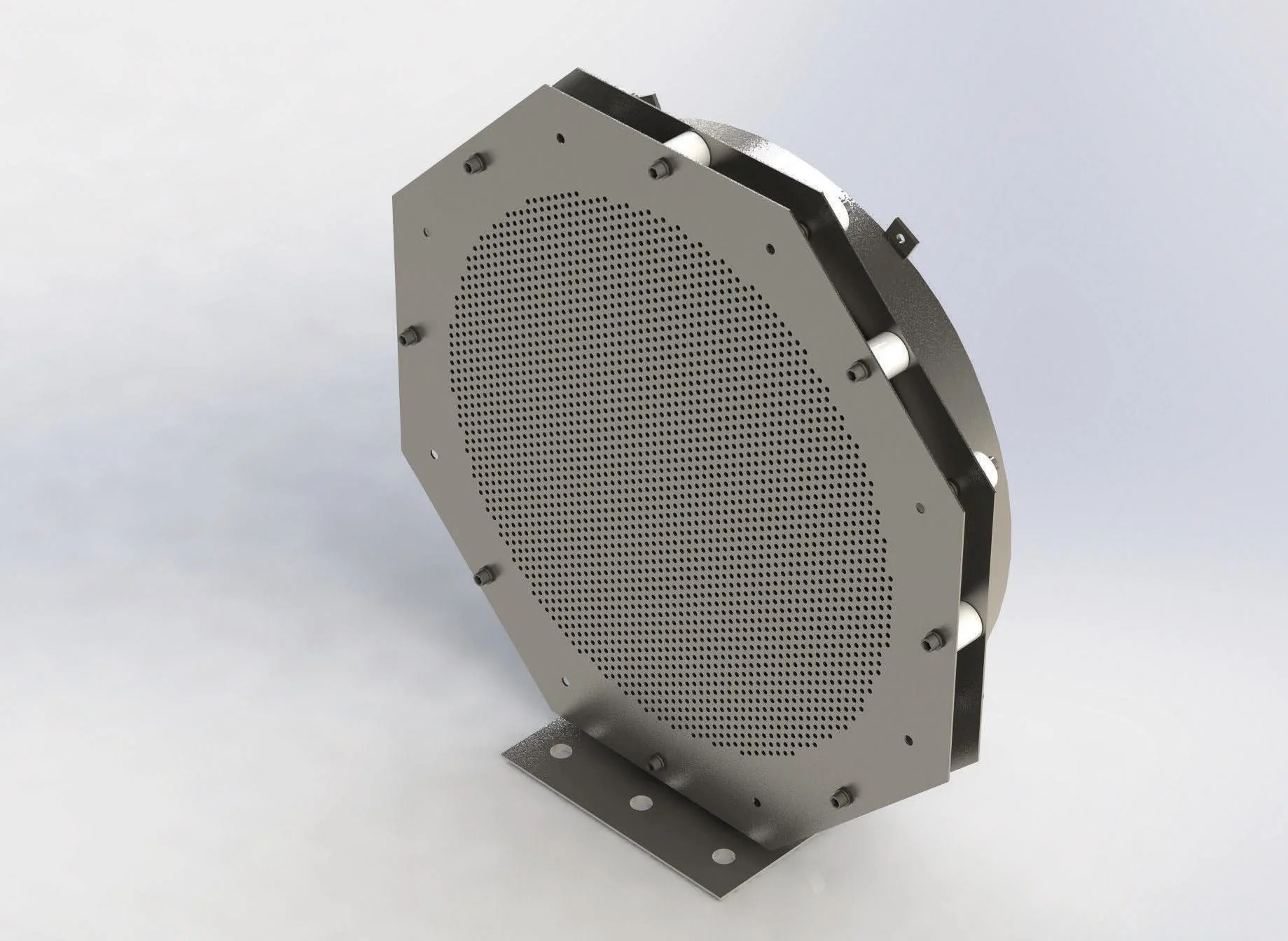
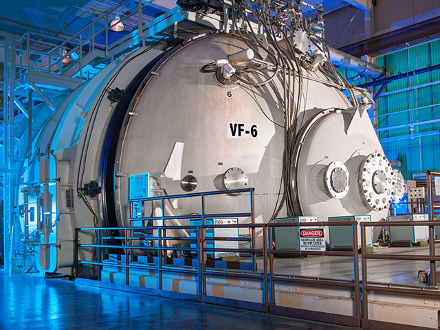
We also visited the Electric Propulsion and Power Laboratory (EPPL). NASA engineers tested the ion engines at this facility in preparation for Deep Space 1, which was one of the first missions to use an ion engine as the main spacecraft engine. Ion thrusters work by first ionizing a volume of xenon gas. Ionization removes electrons from the gas and leaves the xenon atoms positively charged. A pair of grids at the aft end of the thruster is charged to a very high voltage difference, which accelerates the xenon ions to high speeds through the holes in the grids. This makes for efficient but low-thrust rocket engines. See the upper image for one of these mesh grids. This facility has large vacuum chambers to simulate extreme deep-space environments. See the lower image for one of its vacuum chambers.
Information credit: NASA Glenn H.S. Engineering Institute